

We build the power supply as part of the audio component.
See how Sharada Audio turns alternating-current mains power into stable, purpose-built direct-current rails for streamers, reclockers, digital-to-digital converters, digital-to-analog converters, and amplifiers.
We accept the added size, weight, heat, component count, and construction work of linear power because critical digital and analog circuits deserve a supply designed around their actual load.
1.What does a power supply do inside an audio component?
The wall provides alternating current at mains voltage. Our audio circuits require lower direct-current voltages that remain stable as the AC line and circuit load change. We design that conversion as part of the product rather than treating power as a generic accessory.
1.1The supply converts mains power into usable DC rails.
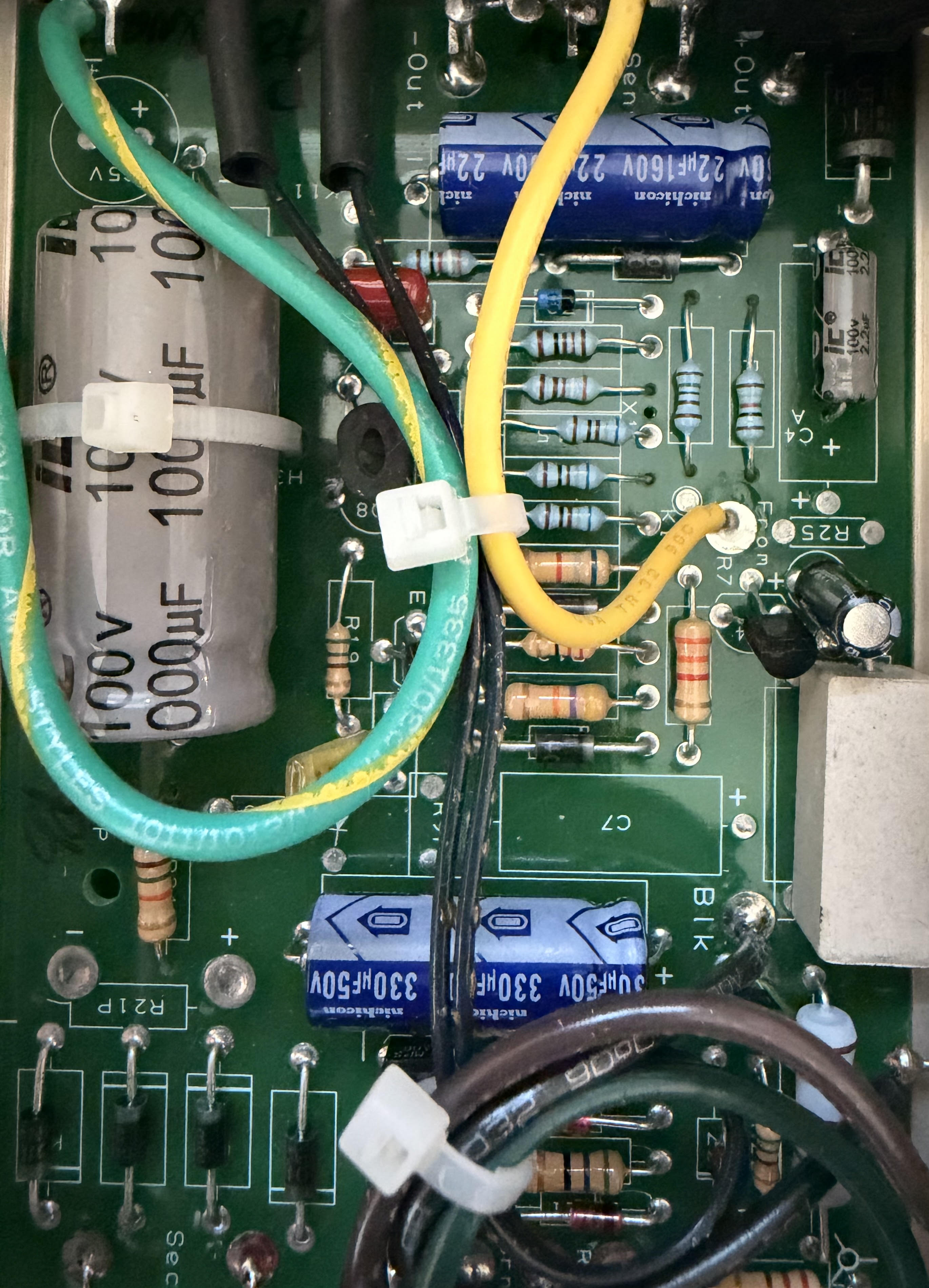
A typical linear supply uses a transformer to change and isolate the mains voltage, a rectifier to turn alternating current into pulsating direct current, reservoir capacitors to store energy and reduce the large ripple, and a regulator to hold the final rail near its intended voltage.
1.2Different circuits may require different rails.
Computer modules, clocks, Universal Serial Bus (USB) interfaces, Field-Programmable Gate Arrays (FPGAs), digital receivers, Digital-to-Analog Converter (DAC) stages, and analog outputs do not necessarily use the same voltage or draw current in the same way. Separating or locally regulating these loads can prevent one section from unnecessarily disturbing another.
2.How is a linear power supply different from a switching supply?
Both designs can produce regulated power. We choose linear supplies for critical Sharada Audio rails when their low-noise behavior, predictable construction, and absence of a local high-frequency switching stage are worth the additional size and heat.
2.1A linear supply regulates without a high-frequency switching stage.
After the transformer, rectifier, and reservoir capacitors establish an unregulated DC voltage, a linear regulator continuously drops the excess voltage to hold the output rail steady. The approach is simple and can be very quiet, but the unused voltage becomes heat.
2.2A switching supply controls power through rapid switching.
A Switch-Mode Power Supply (SMPS) transfers and regulates energy by switching at a frequency far above the mains frequency. It can be smaller and more efficient, but its switching edges, magnetic components, filtering, grounding, and emissions require careful design.
2.3We choose linear power, then do the harder design work around it.
Calling a supply “linear” is not enough. A careless linear supply can still have hum, heat, excessive impedance, or magnetic coupling. We earn the benefit through transformer selection, reservoir capacity, discrete regulation, local filtering, thermal design, short current paths, grounding, shielding, and deliberate physical separation.
3.How does a linear supply turn AC mains power into a stable rail?
Each stage solves a different problem. We specify the transformer, rectifier, Nichicon reservoir capacitors, regulator, and local filters as one supply built around the product it powers.
3.1The transformer changes voltage and provides galvanic isolation.
The transformer converts the incoming mains voltage to the lower alternating voltage required by the supply. It also separates the secondary circuit from a direct conductive connection to the mains. Transformer rating, regulation, magnetic field, mechanical vibration, and placement all matter.
3.2The rectifier converts AC into pulsating DC.
Diodes conduct during part of each mains cycle and charge the reservoir capacitors. These charging pulses can create high peak currents, electromagnetic fields, and voltage drops, so rectifier choice, loop area, wiring, and grounding deserve deliberate treatment.
3.3Reservoir capacitors store energy between charging peaks.
The reservoir supplies the load while the rectified waveform falls between peaks. Its capacitance, current rating, Equivalent Series Resistance (ESR), wiring impedance, transformer, and load together determine the unregulated rail's ripple and recovery behavior.
3.4The regulator holds the final output near its target voltage.
The regulator reduces the remaining ripple and responds when input voltage or load current changes. It needs enough voltage across it to remain in regulation, enough thermal capacity to dissipate heat, and suitable local capacitors to remain stable.
4.What do ripple, regulation, and transient response mean?
We pay attention to all of these behaviors because an impressive ripple figure alone does not describe a complete supply. The rail must remain quiet, regulated, stable, and responsive at the actual powered circuit.
4.1Ripple is the remaining periodic variation on the DC output.
Reservoir ripple normally follows the rectified mains frequency. A regulator and local filtering reduce how much of that variation reaches the powered circuit. The relevant result is the noise that appears at the actual rail and frequency range used by the load.
4.2Line and load regulation describe voltage accuracy under change.
Line regulation describes how the output changes as the input voltage changes. Load regulation describes how it changes as the circuit draws more or less current. Tight regulation helps keep a circuit inside the operating conditions for which it was designed.
4.3Transient response describes recovery after a rapid load change.
Digital processing, interface activity, clock distribution, relay operation, and analog output stages can change the current drawn from a rail. The rail may briefly dip or overshoot before the supply settles. Useful transient testing records the size of that deviation, the ringing, and the time required to return within tolerance.
4.4Low output impedance helps the rail remain stable at the load.
The regulator specification is only part of the path. Circuit-board traces, connectors, wire length, grounding, and local decoupling add impedance between the regulator and powered circuit. Short current paths and local capacitors help supply rapid current close to the load.
5.Why do mains filtering, grounding, and physical layout matter?
This is where construction quality becomes visible. A quiet regulator can still be undermined by magnetic coupling, large current loops, shared return paths, unsafe mains routing, or high-frequency noise entering through the power line.
5.1Mains filtering reduces conducted high-frequency noise.
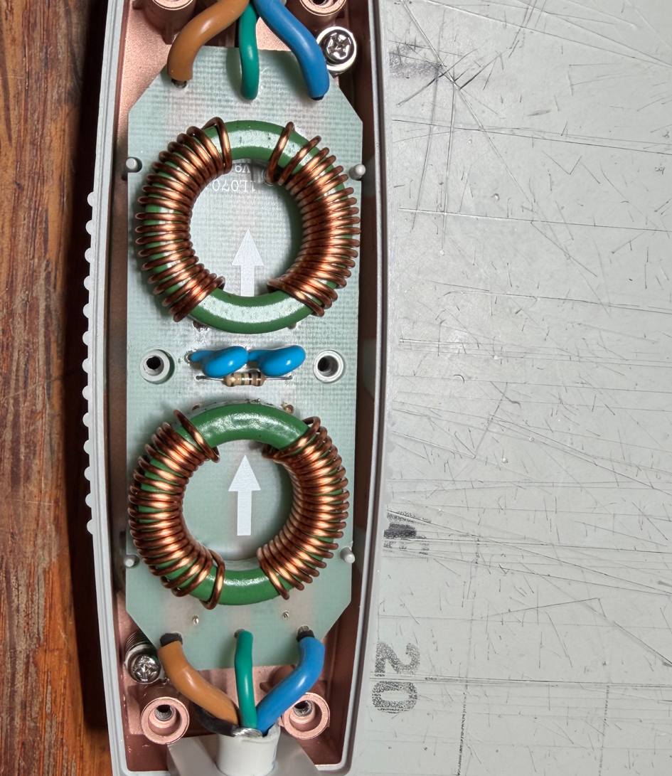
An Electromagnetic Interference/Radio-Frequency Interference (EMI/RFI) filter uses safety-rated capacitors and common-mode chokes to attenuate unwanted high-frequency energy entering or leaving the product. It must be designed around mains safety, protective earth, leakage current, current capacity, and the applicable regulations.
5.2Transformer placement reduces magnetic coupling.
Distance, orientation, shielding, chassis material, and wiring position affect how strongly the transformer's field couples into low-level analog circuits, clocks, and signal wiring. Physical placement is therefore part of the electrical design.
5.3Grounding must separate safety from signal-flow decisions.
Protective earth exists for safety and must not be treated as an optional audio adjustment. Signal returns, chassis bonding, shielding, and high-current charging paths must be arranged so that noisy current does not share an unintended path with sensitive circuitry.
6.Why does each audio product need a different power design?
We do not place one generic supply behind every Sharada Audio product. Each rail is designed around the powered circuit, its current demand, noise sensitivity, thermal behavior, and real operating conditions.
6.1Digital processing and clocks need controlled local rails.
Processors, FPGAs, USB interfaces, network interfaces, oscillators, and clock buffers may require several voltages and local regulation points. Separating high-activity logic from timing-sensitive sections can reduce unwanted coupling through shared supply and ground impedance.
6.2DAC and analog output stages have different current paths.
A DAC may contain digital logic, reference supplies, conversion elements, current-to-voltage stages, output filters, and line drivers. Rail voltage, noise, channel separation, grounding, and local energy storage should be matched to those sections rather than copied from the computer-facing input stage.
6.3Amplifiers require much greater current and thermal capacity.
An amplifier supply must support the intended output power into the loudspeaker load while respecting transformer rating, rectifier current, reservoir ripple, wiring, heat, protection, and the available mains service. The design priorities are not identical to those of a clock or digital receiver rail.
7.What do you receive from this extra power-supply work?
You receive an audio component whose power source was designed with the same care as its signal path. The supply, wiring, grounding, enclosure, and powered circuit are developed as one product.
7.1We match the transformer, reservoir, regulation, and filtering to the load.
Our streamers, reclockers, Digital-to-Digital Converters (DDCs), DACs, volume controls, and amplifiers do not receive one repeated supply recipe. Voltage, current capacity, thermal behavior, capacitance, local filtering, grounding, wiring, and enclosure layout are chosen for the product's circuit and intended operating range.
7.2We evaluate the complete rail where the circuit uses it.
Component brand and capacitor size do not establish performance by themselves. The meaningful result includes mains behavior, transformer regulation, rectifier current, reservoir ripple, regulator stability, transient recovery, output impedance, local decoupling, grounding, temperature, and the voltage seen by the actual load.
7.3We protect the conditions required for consistent playback.
The supply supports the circuits responsible for processing, timing, conversion, and analog output without pretending to rewrite the music data. Our promise is the engineering work itself: lower avoidable electrical noise, stable rails, appropriate current reserve, careful recovery behavior, and construction matched to the product.
Learn how power fits into the complete digital audio systemPlace storage, control, playback, conversion, volume, and amplification into one understandable chain.
Explore Sharada Audio productsSee where dedicated power supplies are used across digital sources, interfaces, DACs, and amplification.
Learn how to match the analog chain after the DACConnect DAC output, volume-control range, amplifier sensitivity, and loudspeaker demand.